27 Results
View results:
Sort by:

RWIND 2 and RFEM 6 can now be used to calculate wind loads from experimentally measured wind pressures on surfaces. Basically, two interpolation methods are available to distribute pressures measured in isolated points across the surfaces. The desired pressure distribution can be achieved using the appropriate method and parameter settings.

Using an example of a steel fiber-reinforced concrete slab, this article describes how the use of different integration methods and of a different number of integration points affects the calculation result.

In many frame and truss structures, it is no longer sufficient to use a simple member. You often have to consider cross-section weakenings or openings in solid beams. In such cases, you can use the "Surface Model" member type. It can be integrated into the model like any other member and offers all the options of a surface model. The present technical article shows the application of such a member in an existing structural system and describes the integration of member openings.

As you may already know, RFEM 6 offers you the possibility to consider material nonlinearities. This article explains how to determine internal forces in slabs modeled with nonlinear material.

In this paper, a novel approach was developed to generate CFD models at the community-level by integrating building information modeling (BIM) and geographical information systems (GIS) to automate the generation of a high-resolution 3-D community model to be employed as an input for a digital wind tunnel using RWIND.
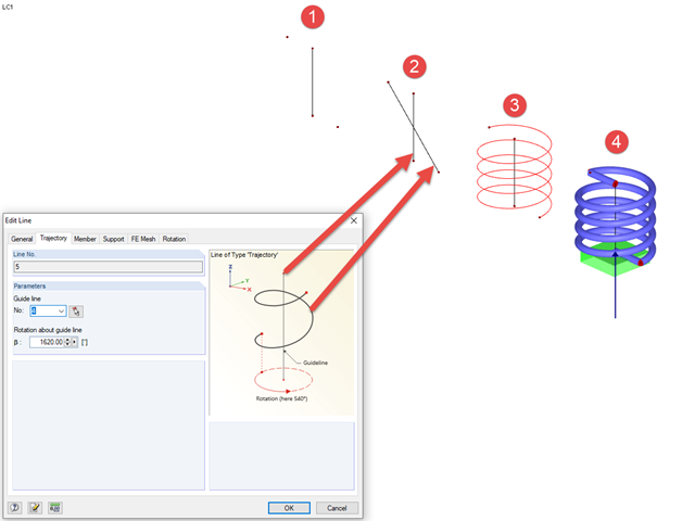
In RFEM, you can create screw lines using the "Trajectory" type line. To do this, you need a center line/guide line around which the line can be modeled, as well as a start and end point. Then, you can create a "Trajectory" type line between the start and end points; this initially appears as a straight line.
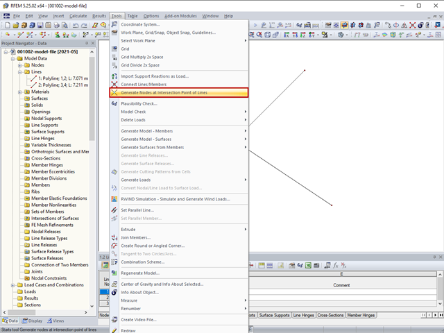
The "Generate Nodes at Intersection Points of Lines" option creates a node at the intersection points of lines without splitting the lines.

In RFEM 5 and RSTAB 8, it is possible to assign nonlinearities to member hinges. In addition to the nonlinearities "Fixed if" and "Partial activity", you can select "Diagram". If you select the "Diagram" option, you have to specify the according settings for the activity of the member hinge. For the individual definition points, it is necessary to specify the abscissa and ordinate values (deformations or rotations and the according internal forces) that define the hinge.
Until now, if you wanted to determine the centroid of a rectangle, it was necessary to define a line from one corner point to the diagonally opposite point. You obtained the centroid by dividing this line. In RFEM 5 and RSTAB 8, you now have the possibility to create a node between two points. Thus, it is sufficient to select the corner points; then you can determine the distance in absolute or relative values.
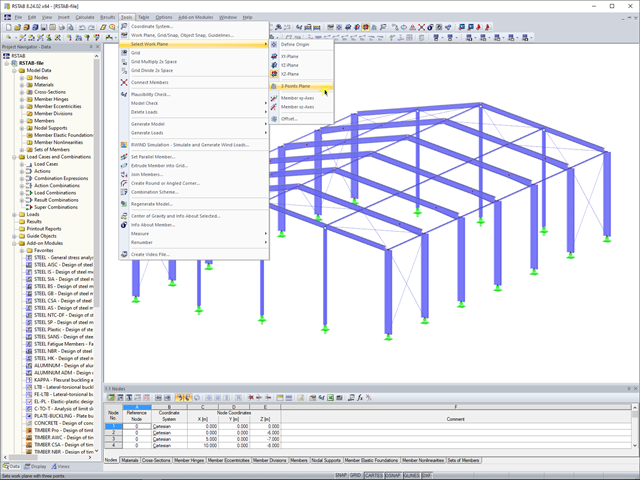
In RFEM 5 and RSTAB 8, you can now create a work plane by simply selecting three points. It is no longer necessary to create a user-defined coordinate system.
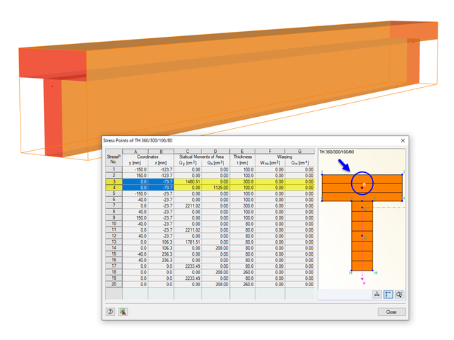
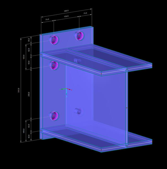
The stresses in the cross‑section of the member are calculated in the stress points. These points are set at locations in the cross‑section where extreme values for the stresses due to the loading types can occur in the material.
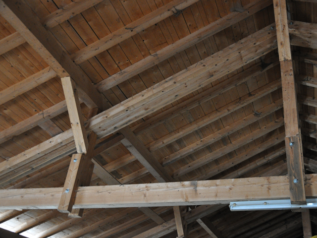
When modeling frame structures, RFEM and RSTAB provide various options for controlling the transfer of internal forces and moments at the connection points of members. You can use the member types to determine whether only forces act on the connected members, or whether moments act on them as well. In addition, you can use hinges to exclude specific internal forces from the transfer. One special form is scissor hinges, which allow for realistic modeling of roof structures, for example.
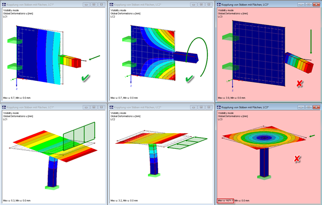
Pay particular attention to the connection points of members and surfaces when you deal with mixed systems, because not all internal forces can always be transferred without difficulty at the coupling location.

The design of cold-rolled steel products is defined in EN 1993-1-3. Typical cross-section shapes are channel, C, Z, top hat, and sigma sections. These are cold-rolled steel products made of thin-walled sheet metal that has been cold-formed by roll-forming or bending methods. When designing the ultimate limit states, it is also necessary to ensure that local transverse forces do not lead to compression, crippling of the web, or local buckling in the web of the sections. These effects can be caused by local transverse forces by the flange into the web, as well as by support forces at the supported points. Section 6.1.7 of EN 1993-1-3 specifies in detail how to determine the resistance of the web Rw,Rd under local transverse forces.
If you read out the results of a surface by means of the COM interface, you get a one-dimensional field with all results at the FE nodes or grid points. To get the results on the edge of a surface or along a line within the surfaces, you have to filter out the results in the area of the line. The following article describes a function for this step.

In RF-PUNCH Pro, enlarged column heads can be arranged at point-supported punching shear points, thus increasing the shear force resistance of a reinforced concrete floor. In the following article, we will show the punching shear design with the optional application of an enlarged column head.

When evaluating line support forces, implausible diagrams sometimes arise at first glance. In particular, for variable loads at locations that also have a nodal support, at division points and edge locations of supported lines, the results sometimes show unexpected support reactions. Using the function of the linear smooth distribution in Project Navigator – Display does not always lead to the expected result diagram.
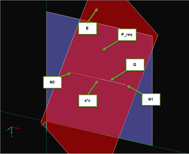
In particular when the adjacent area of connection points should be analyzed, the geometry or load of the connection does not correspond to the standard specifications, and/or a structure should be analyzed with an FE model (for example, in plant engineering), it is necessary to evaluate the connections in detail on the FE model.
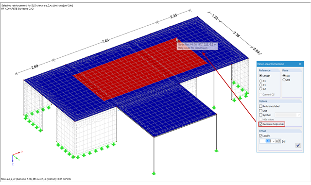
In RFEM and RSTAB, you can add user‑defined dimension lines to a structural model. When creating these dimension lines, click the objects (for example, end nodes of a line, members, and so on) that represent the reference points of the dimension. If you want to add a dimension line free from the structure previously defined in the model, you have to create an additional free "help node" that acts as a reference object for the new dimension.
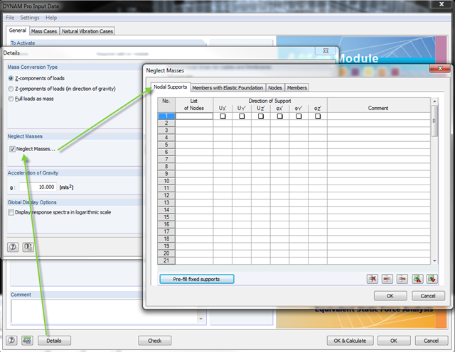
In the DYNAM Pro add‑on module for RSTAB, you can now neglect masses that may have a negative effect on the equivalent mass factor when calculating eigenvalues. To do this, you can disable the masses under [Details]. These include primarily mass points located in the support of the structures.
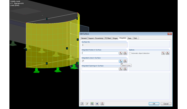
RFEM facilitates modeling by the automatic integration of objects into surfaces. However, it is impossible to integrate the objects automatically in the case of curved surfaces. For manual integration, select the relevant surfaces and click the "Edit Surfaces" option in the shortcut menu; then, in the "Integrated" tab, you can integrate the relevant objects using the "Select" function. This way, you can avoid error messages caused by non‑integrated objects when starting the calculation.
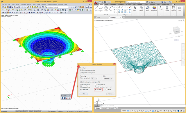
In RFEM, there are a file‑based and a direct DXF interface. The file-based DXF interface allows you to export the data in a DXF file that is transferred directly into an open AutoCAD file. In the interface dialog box, you can select which data are to be exported (results as isolines, result values, or finite element mesh with boundary and integration lines).
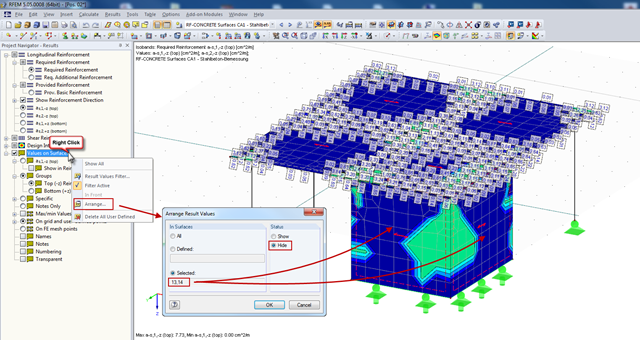
In RFEM, you can display the result values of surfaces (from RF‑CONCRETE Surfaces, for example), which can specify the required reinforcement of the designed surfaces in grid points. Generally, the result values are initially displayed for all surfaces designed.
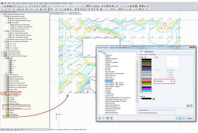
You can document the results of RF‑CONCRETE Surfaces graphically in the printout report. To do this, the "Values on Surfaces" setting is often selected in the Results Navigator of RF‑CONCRETE Surfaces. A text bubble including a result value is displayed, and depending on the settings in the Results Navigator, it can be displayed on the surface grid points, manually defined points, or in FE mesh points.

In RF-CONCRETE Surfaces, you can use the "Filter Points" function when evaluating results by points. This filter function allows for a user-defined group of points that can be defined in the result window. You can select the filter in Window 2.3 Required Reinforcement by Points, among others.
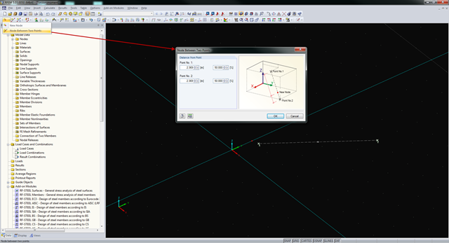
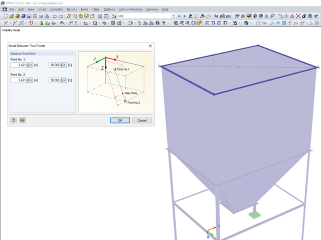
In RFEM and RSTAB, you can create nodes not only by means of coordinates, but also by means of existing nodes. You can use the "Node Between Two Points" function to create a node located on an imaginary line connecting two nodes. You can enter the distance as a percentage or according to the relative lengths.
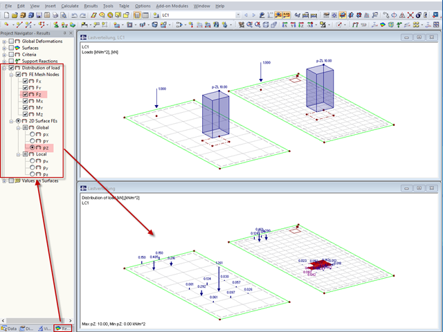
"Distribution of load" represents a load actually applied to the system of FE mesh points or FE surfaces. The FE mesh size plays an important role in the loading in the case of line loads and free loads in particular.